Why RPM alone is not enough—and how surface speed, spray pitch and coating loading influence coating thickness and uniformity
In automated spray coating, achieving a consistent coating thickness is not simply a matter of setting the machine to a particular RPM.
A common approach in production environments is to specify a fixed rotation speed—for example, 30 RPM—and use that value across different components. However, this approach can lead to inconsistent results when the component diameter, coating material, spray gun characteristics or process parameters change.
For ID/OD spray coating applications, the more useful engineering approach is to consider the relationship between:
- Job surface speed
- Coating flow rate
- Job rotation speed
- Gun traverse speed
- Spray pattern width
- Spray overlap
- Coating viscosity
- Atomising pressure
- Target dry film thickness (DFT)
The objective is not simply to find an RPM value. The objective is to establish a repeatable coating process that produces uniform DFT with controlled coating consumption and stable appearance.
This article explains how to approach that problem from an engineering perspective.
1. Why Is Rotation Speed Important in Spray Coating?
During ID/OD spray coating, the component rotates while the spray gun deposits coating onto its surface.
The job should rotate sufficiently fast to minimise circumferential variation in coating thickness. At the same time, excessive rotation speed can introduce other process problems related to centrifugal effects, atomisation and coating flow.
The fundamental principle is:
The rotation speed should be selected as part of the overall coating process—not as an isolated machine parameter.
The source methodology recommends beginning with a surface-speed calculation and then optimising the process according to spray gun characteristics and coating rheology.
2. Surface Speed: A Better Starting Point Than RPM
For a rotating cylindrical component, the surface speed is related to component diameter and rotational speed.
The basic relationship is:
Where:
- V = surface speed in m/s
- D = component diameter in metres
- N = rotation speed in RPM
Therefore:
This equation provides an important engineering insight:
The same RPM does not produce the same surface speed when component diameters change.
Example
Consider an OD coating application where:
- Component diameter = 100 mm
- Target surface speed = 0.15 m/s
Converting the diameter:
Therefore:
So the machine would operate at approximately 29 RPM.
This is only a starting point. The actual optimum must be established experimentally for the particular coating and spray process.
3. Why There Is No Universal RPM Setting
There is no single RPM value that can be applied to every ID/OD coating application.
The appropriate surface speed depends on several interacting process parameters, including:
- Spray gun flow rate
- Spray fan width
- Gun-to-job distance
- Coating viscosity
- Atomising pressure
- Required DFT
- Number of passes
- Gun traverse speed
- Component diameter
- Coating chemistry
The source document suggests an initial development range of approximately 0.10–0.30 m/s surface speed, followed by experimental optimisation.
For a 100 mm OD, this corresponds approximately to:
| Surface Speed | Approx. RPM |
|---|---|
| 0.10 m/s | 19 RPM |
| 0.15 m/s | 29 RPM |
| 0.20 m/s | 38 RPM |
| 0.25 m/s | 48 RPM |
| 0.30 m/s | 57 RPM |
These values should be treated as development starting points, not universal specifications.
4. Coating Deposition per Revolution
Rotation speed becomes even more meaningful when considered together with coating flow.
Suppose:
- Coating flow rate = Q g/min
- Job rotation = N RPM
The coating supplied per revolution can be represented as:
Where:
- = coating supplied per revolution
- = coating flow rate
- = RPM
Example
Suppose the coating flow rate is:
and:
Then:
This gives the process engineer a useful way of looking at coating deposition.
Instead of asking only:
“What RPM should we use?”
we can ask:
“How much coating is being delivered during each revolution of the component?”
The source document identifies coating deposited per revolution as an important consideration for achieving uniform DFT.
5. Rotation and Gun Traverse: The Two-Motion Problem
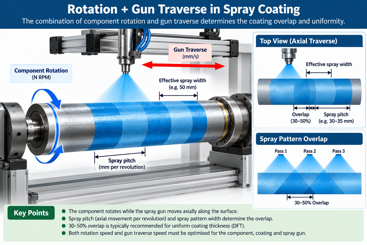
For an OD cylindrical component, the coating process normally involves two simultaneous motions:
1. Component rotation
The component rotates around its axis.
2. Gun traverse
The spray gun moves axially along the component.
The combination of these two motions determines how the spray pattern progresses across the component.
Consider:
- OD = 100 mm
- Circumference ≈ 314 mm
- Rotation = 30 RPM
At 30 RPM, the component completes:
or:
If the gun moves axially at a defined traverse speed, the distance travelled by the gun during one complete revolution determines the spray pitch.
This is a critical parameter because it controls the longitudinal relationship between successive spray passes.
6. Spray Pattern Width and Overlap
Simply knowing the gun traverse speed is not sufficient.
The effective spray width also needs to be considered.
Suppose the effective spray width on the component is:
50 mm
If the gun advances:
100 mm per revolution
then the next pass can leave a substantial gap between coated areas.
This can result in DFT variation and incomplete or non-uniform coating coverage.
A process may instead be designed around an overlap of approximately 30–50%, depending on the application and spray characteristics.
For example, with a 50 mm effective spray width, a 30% overlap gives an approximate effective pitch of:
The exact process value should be established through trials.
This illustrates why RPM alone cannot define a coating process.
7. ID Spray Coating Requires Additional Consideration
The same basic surface-speed concept can be applied to internal diameter coating, using the ID of the component.
However, ID coating introduces additional process considerations.
One important factor is the effect of rotation on the wet coating.
Depending on coating viscosity and wet film thickness, excessive rotation can influence coating movement and may contribute to non-uniformity.
Therefore, the source methodology recommends beginning ID coating development at lower surface speeds and establishing the process experimentally.
Gun positioning is also particularly important for ID applications.
Important parameters include:
- Nozzle-to-wall distance
- Nozzle centering
- Spray angle
- Gun insertion speed
- Gun extraction speed
- Spray pattern
- Overlap
For complex internal geometries, these factors can become just as important as the rotational speed.
8. A Better Way to Think About DFT Uniformity
Imagine looking at the circumference of the component as a clock.
The spray gun deposits coating over a certain angular region.
As the component rotates:
0° → 90° → 180° → 270° → 360°
the complete circumference passes through the spray zone.
The objective is for every revolution to produce a substantially consistent deposition pattern.
This means that DFT uniformity is fundamentally connected to the relationship between:
Angular movement + coating deposition rate
Consequently, spray flow and RPM need to be considered together rather than independently.
9. The Three Parameters That Matter Most
For automated coating machine development, a more robust methodology is to focus on three fundamental parameters.
1. Surface Speed – m/s
Surface speed represents how quickly the component surface moves through the spray zone.
It controls the circumferential exposure of the component.
2. Spray Pitch – mm/revolution
Spray pitch represents the axial distance travelled by the gun during one revolution.
It controls the longitudinal relationship and overlap between successive passes.
3. Coating Loading – g/revolution
Coating loading represents the amount of coating supplied during each revolution.
It connects coating flow rate with component rotation.
Together, these three parameters provide a much more useful engineering framework than simply specifying an RPM value.
10. Example of PLC-Based Recipe Control
Consider an automated Summit coating machine configured with the following recipe:
| Parameter | Example Value |
|---|---|
| Component | ABC-100 |
| OD | 100 mm |
| Target surface speed | 0.15 m/s |
| Calculated RPM | 28.6 RPM |
| Paint flow | 60 g/min |
| Gun distance | 150 mm |
| Gun traverse | 15 mm/s |
| Spray overlap | 40% |
| Target DFT | 20 ± 3 µm |
The important engineering concept is that surface speed is entered as the process parameter, rather than forcing the operator to manually determine RPM.
The PLC can calculate the required RPM based on component diameter.
For example, if the diameter changes from 100 mm to 200 mm, the PLC recalculates the required RPM to maintain the same target surface speed.
This approach makes the machine more adaptable to different component sizes.
11. How Should the Optimum Rotation Speed Be Determined?
The optimum rotation speed should be established through a controlled process-development trial.
One practical approach is a simple Design of Experiments (DOE) or structured trial.
For example:
20 RPM → 25 RPM → 30 RPM → 35 RPM → 40 RPM
While changing RPM, other important process variables should be kept constant.
For every trial, measure:
- DFT at 8–12 circumferential locations
- DFT along the component length
- Coating consumption
- Visual appearance
- Runs and sags
- Overspray
- Transfer efficiency
The objective is not necessarily to achieve the highest average DFT.
Instead, the process should be evaluated based on the combination of:
Low DFT variation + required mean DFT + acceptable coating consumption + stable appearance.
12. From Operator Experience to Engineering-Based Coating
Many coating processes depend heavily on operator experience.
An experienced operator may know that a particular component “works well” at a particular RPM, traverse speed or spray setting.
The challenge arises when:
- Component diameter changes
- A new coating material is introduced
- Spray guns are changed
- Production volume increases
- Different operators run the machine
- DFT requirements become tighter
- Process data needs to be recorded
An engineering-based system converts these experiences into repeatable machine recipes and measurable process parameters.
This is particularly important for automated coating systems where PLC, HMI, servo motion and process monitoring can be integrated.
