Introduction
In an automatic coating machine, the quality of the coating depends not only on the spray gun, coating formulation and process parameters, but also on how effectively the machine manages the air around the spraying operation.
Excess coating mist, commonly referred to as overspray, can contaminate machine interiors, affect the surrounding environment, increase maintenance requirements and compromise process consistency. When solvent-based coatings are used, the extraction system must also address flammable vapours and occupational exposure.
The suction blower is therefore not merely an exhaust component. It is an integral part of the coating process.
At Summit Engineers & Consultants Pvt. Ltd., our approach is to treat the blower, spray enclosure, filtration system, ducting and air-supply arrangement as one integrated engineering system.
This article explains the qualitative considerations and quantitative rules of thumb that can guide the preliminary design of an extraction system for an automatic coating machine.
1. Start with the application, not the motor rating
A common mistake is to begin by asking whether the machine requires a 1 HP, 3 HP or 5 HP blower.
Motor power is an outcome of the design, not the starting point.
The first questions should be:
- What is the purpose of the extraction system?
- Where is the overspray generated?
- How much air must be extracted to control the spray mist and solvent vapour?
- What resistance will filters, ducts and bends create?
- How will the system perform as the filters accumulate coating deposits?
- What safety provisions are required for the particular solvent?
A blower that delivers a large airflow under free-discharge conditions may deliver considerably less airflow when connected to a restrictive filter and duct system.
The correct selection must therefore be based on the required airflow at the operating static pressure.
2. Qualitative rules of thumb: What should the engineer look for?
Rule 1: Capture the contaminant at its source
The objective is not simply to move air through the machine. It is to capture overspray before it escapes the intended working zone.
The extraction arrangement should be evaluated against the spray-gun position, component geometry, direction of spray, conveyor movement and enclosure openings.
Poorly positioned extraction can create dead zones in which mist accumulates or allow contaminated air to escape through access openings.
Rule 2: Maintain a controlled airflow pattern
Air should move predictably from the intended clean-air entry points towards the extraction zone.
Uncontrolled turbulence, excessive cross-drafts or poorly positioned air inlets can disturb the spray pattern, increase coating losses and reduce capture efficiency.
For an automatic machine, airflow should be evaluated under actual production conditions, including component movement and simultaneous operation of all spray guns.
Rule 3: Treat filtration as part of blower selection
The filter is not an accessory that can be added after the blower is selected.
Its pressure drop directly affects the operating point of the fan. As overspray accumulates, resistance may increase and extraction performance may decline.
The design should therefore consider:
- Clean-filter pressure drop.
- Final permitted filter pressure drop.
- Filter loading and replacement frequency.
- Coating compatibility and disposal requirements.
- Differential-pressure or airflow monitoring.
Rule 4: Consider solvent vapour separately from overspray
Overspray is primarily an airborne droplet or particulate-capture problem. Solvent vapour is a gas-phase contamination and flammability problem.
A filter that captures coating droplets does not necessarily remove solvent vapour.
The extraction system must account for both hazards. Depending on the formulation, additional vapour treatment or other controls may be necessary.
Rule 5: Make safety a design input
The solvent Safety Data Sheet (SDS) should be reviewed before finalising the blower arrangement.
The design must address hazardous-area classification, ignition sources, suitable fan construction and electrical equipment, grounding and bonding, safe exhaust discharge, and the required operating interlocks.
An ordinary industrial blower should not be assumed suitable for flammable solvent service simply because it has a suitable motor rating.
3. Quantitative rules of thumb: The basic calculations
Rule 6: Calculate airflow from the effective opening area
For an opening through which air is intended to enter or pass, a basic airflow relationship is:
Airflow = Effective area × Average air velocity
In practical units:
Q (m³/h) = A (m²) × V (m/s) × 3,600
Where:
- Q = volumetric airflow in cubic metres per hour.
- A = effective opening or cross-sectional area in square metres.
- V = average air velocity through that area in metres per second.
For example, consider an opening with an effective area of 0.50 m² and an illustrative average velocity of 0.50 m/s.
Q = 0.50 × 0.50 × 3,600
Calculated airflow = 900 m³/h.
This is a mathematical example, not a recommended design velocity for every coating machine. The appropriate velocity depends on the enclosure arrangement, spray process, solvent characteristics and applicable safety requirements.
For an enclosed machine without an open spray face, airflow must be established using the actual air inlets, capture arrangement, solvent-vapour generation and required safety performance. The opening-area formula alone is insufficient.
Rule 7: Check the solvent-vapour dilution requirement
For solvent-based spraying, the required ventilation may be governed by the rate at which solvent vapour is generated, rather than by overspray capture alone.
The engineer should establish:
- The maximum coating consumption rate.
- The solvent fraction in the coating.
- The fraction of solvent that evaporates during the relevant operating period.
- The solvent's lower explosive limit (LEL).
- The permitted design concentration under the applicable code and risk assessment.
The solvent-vapour ventilation requirement should then be calculated using an appropriate recognised method.
Where several volatile solvents are present, their combined flammability contribution must be assessed. A single generic airflow multiplier cannot safely cover every solvent formulation.
Rule 8: Calculate total system resistance
The blower must overcome the resistance of the complete air path.
This includes:
- Enclosure and inlet losses.
- Overspray filter pressure drop.
- Additional filter or treatment-stage losses.
- Duct friction.
- Bends, transitions and dampers.
- Exhaust outlet losses.
The design pressure should be calculated at the required airflow and at the specified filter-loading condition.
A practical principle is to obtain the fan performance curve and confirm that the operating point meets the required airflow at the calculated system resistance.
Rule 9: Estimate the required power only after airflow and pressure are known
A useful preliminary power relationship is:
P (kW) = Q (m³/s) × ΔP (Pa) ÷ (1,000 × η)
Where:
- Q = design airflow in cubic metres per second.
- ΔP = relevant fan pressure rise in pascals.
- η = appropriate overall fan efficiency for the calculation.
For example, suppose a preliminary design requires 2,500 m³/h at a pressure rise of 1,200 Pa, and an assumed overall efficiency of 60%.
Airflow in cubic metres per second:
2,500 ÷ 3,600 = 0.694 m³/s.
Estimated power:
0.694 × 1,200 ÷ (1,000 × 0.60) = 1.39 kW.
This is an illustrative power estimate, not a blower recommendation. The pressure definition and efficiency must be consistent with the selected fan's performance data. The final motor selection must also account for the fan's power curve, starting requirements, operating range and applicable design provisions.
Rule 10: Validate the design on the actual machine
Calculation is the starting point; commissioning establishes whether the machine performs as intended.
Useful verification checks include:
- Airflow at the relevant openings or extraction points.
- Static pressure across filters and at defined duct locations.
- Extraction performance with clean and loaded filters.
- Airflow distribution and escape of visible overspray.
- Required solvent-vapour and flammability controls.
- Interlock operation and post-spray purge.
- Motor current and operating stability.
Measurements should be taken using suitable instruments and a documented test procedure.
4. A practical design sequence for coating-machine manufacturers
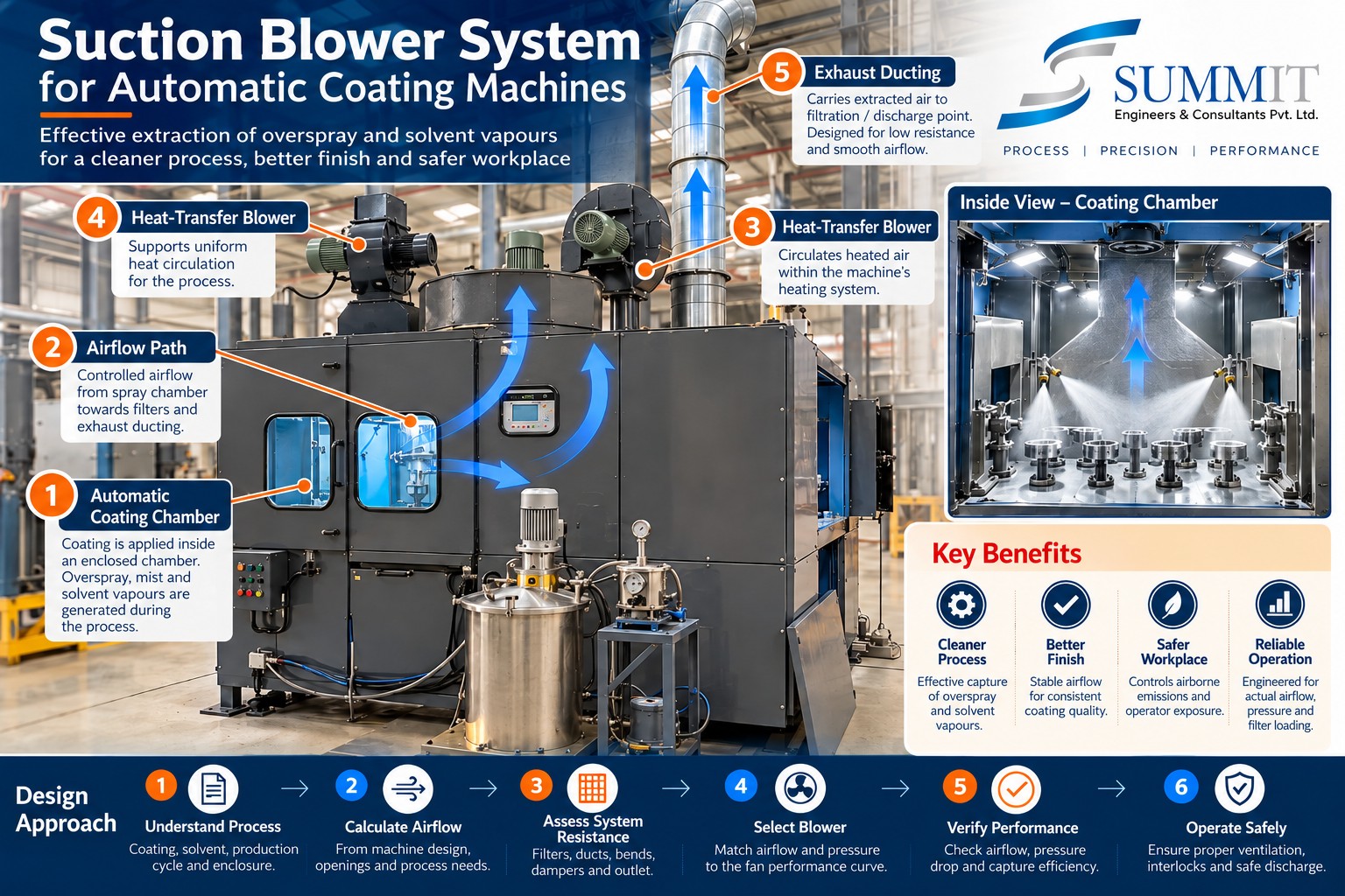
A disciplined design process can be organised into six steps:
Step 1 — Define the process: Identify the coating formulation, solvent composition, spray method, coating consumption and production cycle.
Step 2 — Define the enclosure: Establish its dimensions, openings, component movement, spray-gun locations and air-supply arrangement.
Step 3 — Determine the required airflow: Evaluate overspray capture, opening velocities where applicable, solvent-vapour generation and applicable safety criteria.
Step 4 — Calculate system resistance: Account for filters, ducts, bends, dampers, exhaust treatment and filter-loading conditions.
Step 5 — Select the blower: Use the required airflow and pressure to select the fan, impeller, casing, motor, drive and control arrangement.
Step 6 — Test and document: Verify performance under representative production conditions and document the measured operating parameters.
Conclusion
The correct suction blower is not necessarily the one with the highest motor power or the largest free-air delivery. It is the one that provides the required airflow at the required pressure while maintaining effective overspray capture, appropriate solvent-vapour control and safe operation.
For coating-machine manufacturers, the most useful rule of thumb is simple:
Design the airflow first, calculate the system resistance second, and select the blower and motor only after those requirements are established.
At Summit Engineers & Consultants Pvt. Ltd., we believe that sound coating-machine design comes from integrating process knowledge, airflow engineering, filtration and safety into one coordinated system.
Engineering note: The numerical examples in this article are intended for preliminary engineering understanding. Final designs must be verified against the actual coating formulation, equipment configuration, applicable Indian requirements and relevant recognised standards.